299
Service Tools
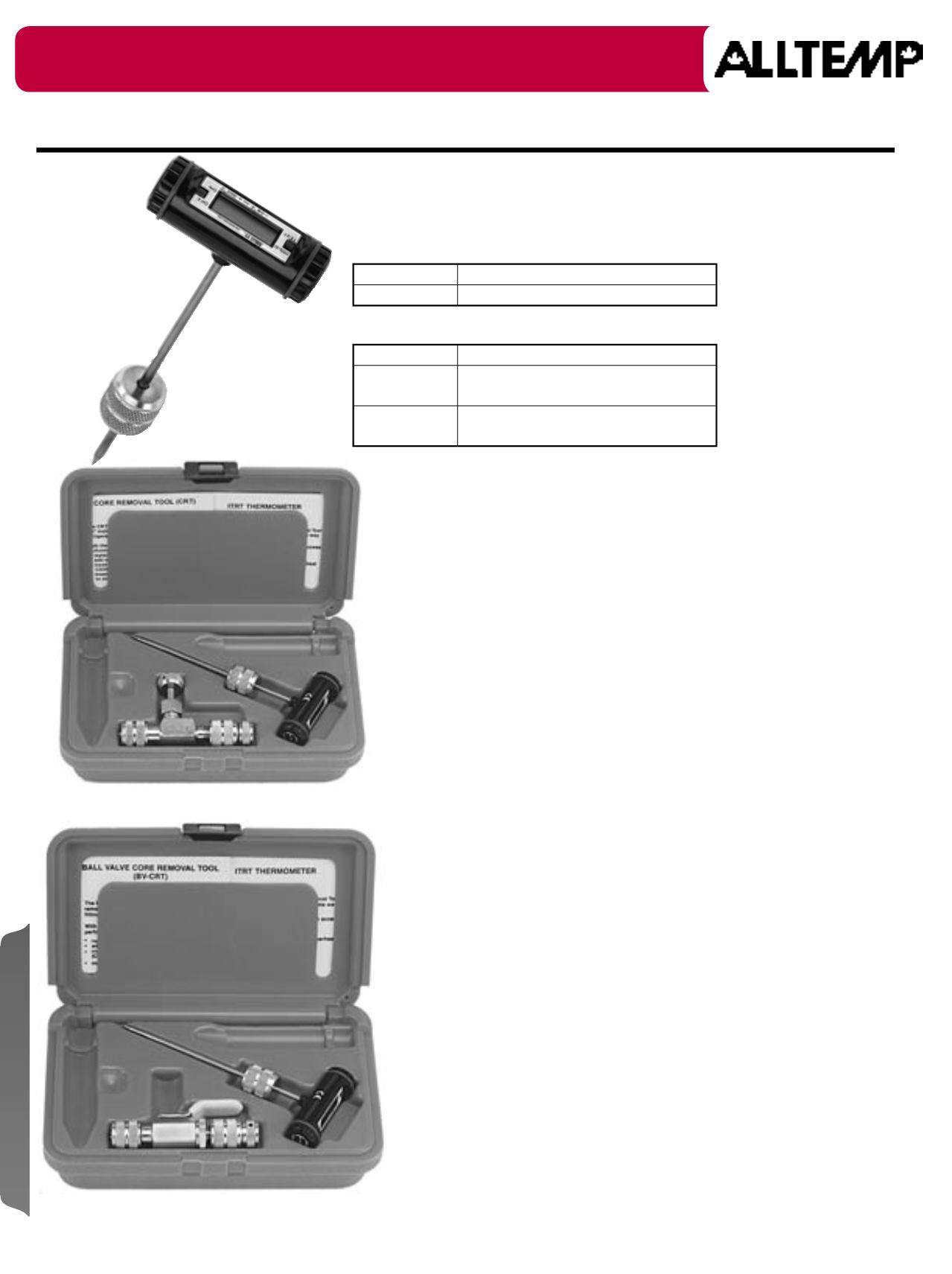
Superheat Tube Thermometer Kits
Tube Thermometer
Part #
Description
02-CD3975
Temperature Range: -58°F to 302°F
Superheat Kits
Part #
Description
02-CD3970
Original CRT Kit - Combines 02-CD3910
& 02-CD3975 thermometer.
02-CD3990
BV CRT Kit - Combines 02-CD3930 &
02-CD3975 thermometer.
Superheat Line Thermometer
A thermometer to obtain a temperature reading through an access
fitting for calculating superheat.
Features
• LCD read out.
• Swivel head.
• On/ Off switch.
• Hold/ Test switch.
• Spare battery
02-CD3990
Illustrated
Instructions for Accurate Superheat
Step 1. Remove Valve Core
Attach the valve core removal tool to the 1/4" male flare fitting on the suction
line thumb tight. With side shut-off valve open completely, push extractor in to
engage the valve core. Rotate the extractor knob counter clockwise to unscrew
the core. Pull the extractor back as far as possible to allow the shut-off valve to
be closed. Close shut-off valve completely by rotating clockwise. Remove rear
coupler, extractor rod and valve core.
Step 2. Insert Thermometer
Insert the thermometer and rotate the coupler clockwise until thumb tight.
Open shut-off valve completely and insert thermometer as far as it will go.
Step 3. Attach Manifold
Attach manifold or low side gauge to the 1/4" access port on the side of the
core removal tool.
Step 4. Read the Temperature and Pressure of the Refrigerant
Step 5. Determine Superheat
Referring to a refrigerant "Pressure/Temperature" chart, determine the
saturation temperature corresponding to the suction pressure measured.
Subtract the saturation temperature from the actual temperature measured.
The difference is the superheat of the refrigerant at the point measured. Adjust
the expansion valve accordingly or adjust the system charge on cap tube
systems.
Step 6. Determine Sub Cooling (If Needed)
Follow Steps 1 - 4 with an access fitting properly located on the liquid line to
obtain the actual internal temperature and pressure. Referring to a refrigerant
"Pressure/Temperature" chart, determine the condensing temperature for
the pressure measured. Subtract the actual temperature measured from
the condensing temperature to get true sub-cooling. Make any equipment
adjustments that are needed.
Step 7. Replace Valve Core
Reverse procedure in Steps 1 and 2 to replace valve core. Be sure that shut-off
valve is open or closed completely as required.
TIPS:
Follow equipment manufacturer's recommendations for adjustment of
superheat and sub-cooling. The superheat measurements required for the
adjustment of a thermal expansion valve should be made as near the outlet
of the evaporator as possible. If no 1/4" access valve is near the outlet of the
evaporator, a V-series or M-series valve mounted on the suction line near the
evaporator can provide the necessary access.
02-CD3970
Illustrated
02-CD3975
Illustrated
C&D
valve mfg. co
Service Thermometers


